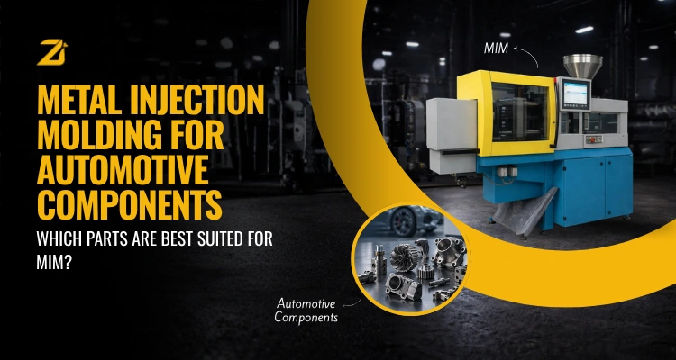
Metal Injection Molding for Automotive Components: Which Parts Are Best Suited for MIM?
 Digvijaysingh Rao
on
Introduction
An automotive sourcing team can specify Metal Injection Molding for a part and still get the wrong outcome. MIM is not universally better than machining, casting, or stamping. It is better for a specific category of parts, and worse for others.
The real question is not whether MIM works for automotive components. It is which components on your bill of materials actually benefit from it, and which ones would be a poor technical or commercial fit.
This guide sets out the criteria that decide MIM suitability, maps them against the automotive systems where MIM is routinely specified, and flags where another process is the better choice.
Key Takeaways
- Geometry Decides Fit First: Parts with undercuts, internal channels, thin walls, or multi-feature geometry are strong MIM candidates because these features form in-tool rather than through secondary machining.
- Tolerance Matters As Much As Size: Dimensional capability around ±0.3% to ±0.5% of nominal dimension may be achievable for suitable MIM features. Actual capability depends on the dimension, geometry, alloy, tooling, sintering control, and datum strategy.
- Volume Is the Commercial Filter: MIM commonly becomes more attractive as repeat volume increases, but there is no universal annual-volume threshold. Break-even depends on the part, alloy, tooling strategy, secondary operations, and incumbent process.
- Selected Powertrain and Transmission Parts May Suit MIM: Small valve, locking, selector, and actuator components can be strong candidates when their size, loading, alloy, tolerance, and validation requirements align with MIM.
- Selected Sensor and ADAS Hardware May Suit MIM: Small sensor mounts, brackets, shielding parts, and complex housings can benefit from MIM. Optical-alignment, sealing, and interface features must be validated individually and may require secondary machining.
- Large or Thin-Wall Structural Parts Are Usually a Poor Fit: Body panels, large brackets, and thick load-bearing sections are generally better suited to stamping, forging, or casting.
- Material Choice Affects Suitability As Much As Geometry: Stainless steels, low-alloy steels, and nickel alloys process well through MIM; not every material and section-thickness combination does.
- A Feasibility Review Beats Guesswork: Because suitability depends on geometry, tolerance, volume, and material together, a technical review of the actual part drawing is the only reliable way to confirm fit.
What Makes an Automotive Part a Strong Candidate for MIM?
Four variables decide whether a part suits MIM: geometric complexity, dimensional tolerance, annual production volume, and material requirement. A part that scores well on most of these is usually a good candidate. A part that scores poorly on two or more usually is not.
Geometric complexity is the first filter. MIM, as detailed on Zealot Inc.'s Metal Injection Molding page, forms many undercuts, internal features, and multi-plane features in the molded geometry, followed by debinding and sintering. If a part currently needs several machining setups to reach its final shape, that complexity can allow MIM to reduce secondary machining.
Tolerance is the second filter. Zealot Inc.'s automotive MIM page reports standard tolerances of approximately ±0.3% to ±0.5% of nominal dimension, but capability remains feature- and part-dependent. Actual results depend on geometry, alloy, tooling, sintering control, and the datum scheme. Critical features may require sizing, grinding, or selective machining.
Volume is the commercial filter. MIM commonly becomes more attractive as repeat volume increases, but no annual-volume threshold applies to every component. The break-even point should be calculated from the part drawing, alloy, tooling and cavity strategy, secondary operations, scrap assumptions, forecast demand, and the process being replaced.
Material requirement is the fourth filter. MIM processes stainless steels such as 316L, 17-4 PH, and 420, along with low-alloy steels and nickel alloys, giving automotive engineers a wide but not unlimited material window.
| Factor | Why It Matters | What to Check |
| Geometric complexity | In-tool features can reduce secondary machining and assembly | Undercuts, internal channels, and multi-feature geometry |
| Dimensional tolerance | Capability is feature- and part-dependent; ±0.3% to ±0.5% may be achievable for suitable features | Datum scheme, critical dimensions, and secondary finishing needs |
| Annual volume | Tooling is amortized across repeat production | Forecast demand and a part-specific break-even analysis |
| Material | Alloys and heat treatments respond differently to MIM | Strength, wear, fatigue, corrosion, and temperature requirements |
| Section thickness | Large thickness changes can affect filling, debinding, and sintering | Wall-thickness range and transitions across the part |
Automotive Parts Best Suited to MIM
Powertrain components. Selected small valve, actuator, and timing components may suit MIM when their geometry, loading, alloy, fatigue life, and validation requirements are compatible with the process. High-load parts should be assessed individually rather than treated as automatic MIM candidates.
Transmission parts. Locking pawls, selector levers, and small clutch or shift-actuator components may suit MIM when their size, engagement loads, wear requirements, and tolerance capability align with the process. Larger shift forks and synchronizer components require part-specific feasibility and durability validation.
Locking mechanisms. Lock barrels, latching cams, pawls, striker plates, and seat adjustment components require complex three-dimensional geometry and high cycle fatigue resistance, both suited to net-shape MIM production.
Turbocharger components. Selected variable-vane, nozzle-ring, and wastegate actuator components may suit high-temperature stainless or nickel-alloy MIM. Bearing housings and other larger or highly loaded parts should be evaluated separately for size, thermal fatigue, creep, wear, and finishing requirements.
Braking system parts. Small ABS valve and actuator components may be evaluated for MIM, subject to material validation, process-capability data, fatigue testing, traceability, and customer approval. Safety-critical suitability cannot be established through traceability alone.
Fuel system components. Small valve, filter, and flow-control components may suit MIM, but alloy and heat treatment must be selected for fuel compatibility, pressure, wear, corrosion, and fatigue. 316L stainless steel should not be assumed suitable for every high-pressure or wear-intensive component.
Sensor housings and ADAS components. MIM may suit small sensor housings, mounts, brackets, and shielding parts with complex geometry. Optical-alignment, sealing, and interface features must be assessed individually and may require secondary machining; precision machining can remain the better route for the tightest critical dimensions.
Structural and interior hardware. Small retention hardware, latching features, and connector components may fit MIM when their geometry, section thickness, loading, and volume support the process. Large structural brackets and primary load-bearing parts generally favor stamping, forging, casting, or machining.
Electric vehicle components. Small connector bodies, locking components, sensor hardware, valve components, motor-retention features, and charging-system hardware may suit MIM. Large battery-management housings and power-electronics enclosures generally favor die casting, stamping, extrusion, machining, or engineered polymers.
| Automotive System | Potential MIM Parts | Key Selection Consideration |
| Powertrain | Small valve, actuator, and timing components | Loading, fatigue life, alloy, and validation |
| Transmission | Locking pawls, selector levers, and small actuator parts | Engagement load, wear, and dimensional capability |
| Locking mechanisms | Lock barrels, latching cams, pawls, and seat-adjustment parts | Geometry, cycle fatigue, and surface requirements |
| Turbocharger | Variable-vane, nozzle-ring, and wastegate components | Temperature, creep, fatigue, and alloy compatibility |
| Braking systems | Selected small ABS valve and actuator components | Safety validation, capability data, and customer approval |
| Fuel systems | Small valve, filter, and flow-control components | Pressure, wear, corrosion, fatigue, and fuel compatibility |
| Sensors and ADAS | Small housings, mounts, brackets, and shielding parts | Optical alignment, sealing, and interface tolerances |
| Electric vehicles | Connector bodies, locking parts, sensor hardware, and retention features | Size, material, loading, conductivity, and volume |
Where MIM Is Usually the Wrong Choice
MIM is not the default answer for every metal automotive part. Large body panels, structural chassis members, and thick load-bearing sections generally suit stamping, forging, or casting better, since MIM's shot-weight and section-thickness limits work against very large or very thick geometry.
Very low annual volumes are another common mismatch because tooling has fewer units over which to amortize. CNC machining or investment casting may be more economical, but the decision should be based on a part-specific cost model rather than a fixed annual-volume cutoff.
Extremely simple geometry is a third mismatch. A plain bushing or a basic fastener that a screw machine can produce cheaply does not need MIM's design freedom, so specifying MIM there adds cost without adding value.
MIM vs CNC Machining and Die Casting for Automotive Parts
Once a part clears the geometry, tolerance, volume, and material checks, the next question is how MIM compares with the alternatives an engineering team is likely already using.
CNC machining remains strong for prototypes, low volumes, oversized parts, and features requiring very tight tolerances, although additional setups and machining time can increase unit cost as geometry becomes more complex. Die casting may be preferable for larger, thin-wall nonferrous parts, while MIM may suit smaller intricate parts and ferrous alloys. Tolerance, density, material, part size, and secondary-operation requirements should be compared feature by feature. A full process-by-process comparison, including investment casting and powder pressing, is covered in Zealot Inc.'s MIM vs Die Casting vs Powder Pressing vs Investment Casting guide.
Checking Volume, Tolerance, and Material Before You Specify MIM
Before a part moves toward MIM tooling, three numbers are worth confirming: expected annual volume, the tightest functional tolerance on the part, and the material property the application actually needs, such as strength, corrosion resistance, or magnetic behavior.
A part that clears volume but needs a tolerance MIM cannot hold as-sintered may still work with a light post-sinter machining step on select features, rather than ruling MIM out entirely. The right answer is rarely all-or-nothing.
For a closer look at how alloy choice affects these decisions, see Zealot Inc.'s MIM Materials Guide. For the cost side of the decision, Metal Injection Molding Cost in India covers where MIM overtakes machining and casting on a per-unit basis.
Zealot Inc.'s dedicated automotive MIM page sets out tolerance, material, and quality information by automotive system in more depth. If your team is qualifying a supplier for an upcoming program, confirm the proposed inspection plan, process-capability evidence, PPAP and customer-specific documentation, material traceability, change control, and the certification scope required for the component.
Why Zealot Inc. for Automotive MIM Components
Zealot Inc. is a Metal Injection Molding manufacturer based in Gandhinagar, Gujarat. Its automotive MIM page presents capabilities for selected powertrain, transmission, locking, turbocharger, braking, fuel-system, sensor, and hardware applications using stainless steels, low-alloy steels, and nickel alloys. Suitability must still be confirmed for the specific component and automotive program.
Zealot's automotive MIM page describes dimensional inspection, first article inspection, material traceability, and documented process control across injection molding, debinding, and sintering. Before nomination, buyers should verify the exact inspection plan, capability-study requirements, PPAP and customer-specific documentation, change-control process, and applicable quality-certification scope for their program. Early design-for-MIM input can identify geometry and tolerance conflicts before tooling is committed.
Conclusion
Metal Injection Molding is not a universal answer for automotive components, and it was never meant to be. It earns its place on parts where geometric complexity, tight tolerance, meaningful volume, and the right material come together, and it loses that advantage everywhere else.
Running a specific part through the geometry, tolerance, volume, and material checks in this guide is the fastest way to find out which side of that line it falls on.
Frequently Asked Questions (FAQs)
Read More:
- MIM vs Die Casting vs Powder Pressing vs Investment Casting: Complete Manufacturing Process Comparison Guide
- MIM Materials Guide: How to Choose the Right Alloy for Your Metal Injection Molding Project
- Metal Injection Molding Cost in India: When MIM Becomes More Cost-Effective Than Machining, Casting, and CNC Manufacturing

Digvijaysingh Rao
Head of Sales & Strategy
Digvijaysingh Rao leads sales and business development at Zealot Inc. He works closely with customers to understand their production challenges and recommend solutions that are practical and easy to maintain.