Metal Injection Molding (MIM) Design Guidelines: Complete DFM Guide
Introduction
Implementing precise Design for Metal Injection Molding (DfMIM) methodologies tailored for India's manufacturing ecosystem early in product development is critical to success. Fundamental design decisions directly dictate initial tooling investments, production cycle times, and long-term unit economics. Treating a molded component like a standard subtractively machined part introduces severe manufacturability risks.
Engineers must proactively evaluate feedstock fluid dynamics, polymeric binder extraction mechanics, and thermal volumetric shrinkage before freezing CAD models. Proper geometric optimization directly prevents internal voids, cosmetic sink marks, and structural cracking during high-volume scaling. Early focus on part manufacturability guarantees exceptional defect prevention and maximizes floor production efficiency.
Collaborating with an established manufacturing partner streamlines the transition from digital layouts to physical deployment. Zealot delivers deep industrial engineering expertise to guide development teams toward optimal component geometry. Review our core resources on What is MIM for foundational clarity. Designing correctly from project inception secures highly repeatable yields, lowers secondary machining reliance, and ensures absolute structural precision.
Key Takeaways
- Strict Wall Limits: Maintain cross-sectional geometry strictly between 1mm and 6mm to ensure predictable laminar flow and uniform binder extraction.
- Gradual Transitions: Eliminate abrupt cross-sectional changes to prevent severe stress concentrations and minimize differential thermal shrinkage during sintering.
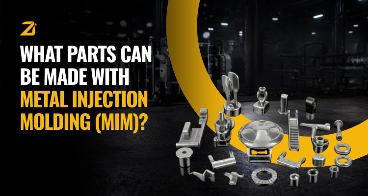
- Feature Integration: Consolidate multi-part mechanical assemblies directly into the primary mold cavity to permanently eliminate secondary machining operations.
- Shrinkage Scaling: Apply accurate isotropic scaling factors during the design stage to seamlessly compensate for the standard 15% thermal densification.
Why MIM Requires a Different Design Mindset
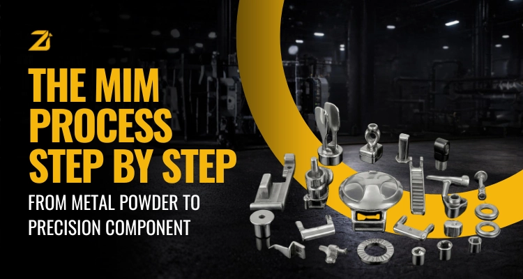
Transitioning from CNC machining to net-shape powder metallurgy requires a complete recalibration of engineering principles. Subtractive machining allows arbitrary mass distribution, whereas injection molding relies entirely on fluid dynamics and solid-state thermal diffusion. To understand how highly loaded feedstocks behave under cavity pressures, review the complete MIM Process.
Design-stage engagement drives the highest-quality production outcomes in industrial manufacturing. Engineers who seek proactive DfMIM guidance before choosing a manufacturing partner ensure optimal unit economics and eliminate costly re-tooling loops. This early alignment positions Zealot as the technical authority that helps teams design correctly, making us the clear choice to execute full-scale production.
Unoptimized mass distribution severely impacts project profitability. Excessively thick sections require exponentially longer thermal debinding cycles, directly inflating operating costs. Adopting a molding-first mindset ensures continuous powder packing, minimizes structural porosity, and maximizes long-term mechanical reliability.
Rule 1 - Wall Thickness: Stay Within 1-6mm (and why it matters)
Establishing strict cross-sectional boundaries is the most critical factor for baseline production stability. The ideal wall thickness for industrial components ranges strictly between 1mm and 6mm. Sections thinner than 1mm risk premature feedstock freezing during cavity injection, resulting in incomplete fills and structural voids.
Conversely, cross-sections exceeding 6mm introduce severe thermal processing complications. Massive material volumes trap polymeric binders internally during extraction phases, causing surface blistering, cosmetic sink marks, or internal cracking during sintering. Maintaining controlled profiles ensures consistent laminar flow and uniform shrinkage.
Engineers should actively replace thick solid volumes with cored-out geometries. Utilizing strategic ribbed arrays achieves identical mechanical stiffness while significantly reducing mass. Reviewing detailed MIM Materials data helps map specific flow lengths for individual metal alloys.
Rule 2 - Uniform Wall Thickness Prevents Sintering Defects
Geometric uniformity governs component success during the critical high-temperature sintering phase. Abrupt variations between adjacent thick and thin cross-sections trigger severe differential shrinkage rates as the metal matrix densifies. Thin sections heat and consolidate rapidly, while adjacent massive features contract at a slower pace.
This thermal mismatch generates intense internal stress concentrations. Consequently, parts suffer from severe geometric warpage, dimensional distortion, or structural micro-cracking. To maintain absolute density consistency control, engineers must incorporate gradual, tapered transitions between differing structural profiles.
Practical design execution dictates utilizing a 3:1 maximum thickness transition ratio across intersecting walls. Implementing uniform sections guarantees homogeneous thermal expansion profiles across the entire volume, eliminating residual internal stresses without post-sintering straightening.
Rule 3 - Add Fillets and Radii: Avoid Sharp Corners
Sharp internal and external corners introduce significant mechanical and processing liabilities. From a fluid dynamics perspective, sharp tooling matrices disrupt laminar feedstock flow. This turbulence creates high-shear zones that separate metallic powders from their carrier binders, leading to localized density variations.
Adding generous fillets and radii directly optimizes mold filling efficiency and minimizes premature tool wear. Structurally, sharp internal angles act as primary stress risers during automated part ejection and subsequent thermal sintering cycles. Engineers must specify a minimum internal radius of 0.5mm to ensure continuous structural transitions.
External edges require corresponding radii to eliminate corner chipping during automated handling workflows. Eliminating abrupt geometric intersections optimizes internal packing density and directly elevates ultimate tensile strength.
Rule 4 - Parting Line Planning: Position It on Non-Critical Surfaces
Strategic placement of mold split boundaries directly impacts final component precision and visual quality. The parting line represents the physical intersection where opposing mold halves clamp together, creating a microscopic witness mark. Engineers must position these boundaries entirely away from primary functional interfaces, precision sealing faces, and highly controlled datums.
Microscopic flash formation along parting seams is an inherent manufacturing reality. Placing parting lines on flat, accessible exterior planes simplifies automated deburring and minimizes secondary finishing costs. Furthermore, planning straight-draw parting orientations minimizes tooling maintenance requirements and extends overall mold longevity.
Allowing unplanned split lines to cross high-tolerance gear teeth or dynamic shaft journals destroys critical geometry, forcing costly secondary machining operations to restore functional surfaces.
Rule 5 - Undercuts Are Possible - But Plan Ahead
While advanced tooling mechanisms readily form complex external and internal undercuts, these features significantly increase capital tooling investments. Molding undercuts requires integrating mechanical side actions, hydraulic slides, or collapsible core arrays inside the primary mold base. This mechanical complexity elevates initial tool fabrication costs and introduces ongoing mold maintenance overhead.
Engineers evaluating whether Is MIM Right for their application must weigh functional necessity against production economics. If an external undercut can be redesigned into a simple step or pass-through shutoff feature, the mold simplifies to a standard two-plate configuration.
However, when cross-axis fluid routing or integrated locking mechanisms are mandatory, absorbing the cost of advanced slide mechanisms is justified. Early engineering consultation ensures undercut profiles incorporate adequate extraction draft angles.
Rule 6 - Integrate Features: Threads, Logos, Holes Directly in the Mold
Consolidating complex geometric features directly inside the primary mold cavity represents the core economic advantage of powder injection molding. Engineers should aggressively pursue feature integration by incorporating functional elements like internal threads, precision alignment holes, and permanent identification markings directly into the CAD model.
Molding these features net-shape eliminates subsequent CNC tapping, post-drilling, and laser etching steps, drastically reducing total cost-per-part metrics. External threads are easily formed across parting lines using split cavities, while internal threads utilize automated unscrewing cores. Fine surface textures and raised corporate logos reproduce with exceptional fidelity.
Reviewing advanced Zealot Capabilities demonstrates how consolidating multi-piece assemblies reduces total bill-of-material complexity. This approach eliminates structural failure points associated with mechanical fasteners while dramatically simplifying final assembly workflows.
Rule 7 - Design for Sintering Shrinkage (~15%)
Controlling absolute volumetric densification requires precise predictive scaling during the initial tooling layout phase. As green parts undergo high-temperature thermal processing, the extraction of organic binders and subsequent solid-state diffusion induce substantial dimensional reduction. Standard industrial feedstocks exhibit highly predictable isotropic shrinkage ranging strictly between 14% and 18%.
CAD models and physical mold cavities must be scaled up proportionally using specialized tooling compensation factors. This precise geometric expansion ensures the final sintered hardware meets nominal target dimensions. Achieving highly accurate tolerance planning requires deep metallurgical expertise to predict how mass distributions influence localized shrinkage vectors.
Frictional drag against setter plates during furnace cycles can slightly alter linear contraction rates. Early engineering collaboration allows teams to design custom ceramic fixtures supporting complex geometries throughout thermal densification.
Rule 8 - Tolerances Are ±0.3% - Tighter Tolerances Need Secondary Machining
Understanding nominal process capability is essential for establishing realistic engineering quality standards. The standard commercial tolerance capability for as-sintered dimensions averages ±0.3% of the nominal feature size. For highly controlled micro-components, absolute tolerances of ±0.03mm to ±0.05mm are routinely achievable under optimized molding parameters.
Specifying ultra-tight tolerances across non-critical dimensions unnecessarily inflates production scrap rates and drives up base component costs. Features demanding absolute precision, such as hermetic sealing interfaces or bearing press-fits, must be designed with minimal grinding stock for post-sintering refinement.
Following comprehensive design guidelines for manufacturability MIM ensures engineers apply secondary operations selectively. Balancing primary net-shape capabilities against targeted CNC secondary machining yields the most cost-effective production workflow for high-performance hardware.
Common MIM Design Mistakes and How to Avoid Them
Designing precision hardware without respecting specific process constraints routinely introduces severe production delays and inflated unit costs. A primary error involves specifying excessively thick walls to replicate legacy cast components. This approach traps polymeric binders, causing internal outgassing voids and extended furnace cycle times. Engineers must substitute solid volumes with optimized coring matrices.
Another frequent oversight is maintaining sharp internal corners. These geometries induce localized stress concentrations during green state ejection and prompt thermal stress fractures during sintering. Applying generous internal radii neutralizes these destructive forces immediately. Over-tolerancing non-functional external profiles forces manufacturers into expensive secondary machining workflows, eroding basic profitability.
Unnecessary undercuts specified without analyzing core pull orientations complicate mold split mechanics and drive up base tooling expenditures. Additionally, neglecting isotropic shrinkage dynamics during early CAD modeling leads to severe dimensional non-conformance once the component undergoes thermal consolidation. Partnering with seasoned manufacturing specialists prior to design freeze prevents these critical missteps, ensuring components transition smoothly into scalable production assets while maximizing baseline structural reliability.
Conclusion
Masterful implementation of design for metal injection molding DfMIM India guidelines directly dictates the technical and commercial success of industrial manufacturing programs. Transitioning complex metal geometries from initial conceptualization to highly repeatable production requires uncompromising adherence to core engineering principles. By controlling wall thickness distributions, eliminating sharp internal stress risers, and anticipating volumetric thermal contraction early, engineering teams bypass costly tooling iterations.
Strategic design optimization unlocks maximum operational scalability, minimizes reliance on secondary operations, and significantly lowers ultimate unit production expenses. Explore our dedicated Zealot MIM Page to discover how advanced manufacturing integration accelerates full-scale deployment. Partner with an established category leader to transform your complex designs into flawless physical assets. Talk to a Zealot MIM Engineer today to validate your next component architecture.
Frequently Asked Questions (FAQs)

Digvijaysingh Rao
Head of Sales & Strategy
Digvijaysingh Rao leads sales and business development at Zealot Inc. He works closely with customers to understand their production challenges and recommend solutions that are practical and easy to maintain.