
Up to 20% off patio Shop now
Up to 60% off summer footwear See more
  • About
  • Busniess Verticals
  • MIM
  • Precision Metal Component Solutions
  • Case Studies
  • Blogs
Up to 20% off patio Shop now
Up to 60% off summer footwear See more
  • About
  • Busniess Verticals
  • MIM
  • Precision Metal Component Solutions
  • Case Studies
  • Blogs
Zealot_Logo_1
✕
Search
Contact
✕
sales@zealotinc.net
+91 9909418224
Zealot_Logo_1
  • Home
  • About
  • Busniess Verticals
    • Cast Polyurethane Elastomer Solution
      • Automatic Cast Polyurethane Elastomer Solution
      • Hand Batch Cast Polyurethane Elastomer Solution
    • Cast Nylon Solutions
    • Machinery Accessories
      • Metering Pump
      • Industrial Hose
      • Pressure Tank
    • Precision Metal Component Solutions
  • MIM
  • Support
    • Consulting
    • Assistance
    • Turnkey Project Solutions 
  • Resource
    • Blogs
    • Case Study
    • Downloads
    • Videos
  • Contact Us
Zealot_Logo_1
  • Home
  • About
  • Busniess Verticals
    • Cast Polyurethane Elastomer Solution
      • Automatic Cast Polyurethane Elastomer Solution
      • Hand Batch Cast Polyurethane Elastomer Solution
    • Cast Nylon Solutions
    • Machinery Accessories
      • Metering Pump
      • Industrial Hose
      • Pressure Tank
    • Precision Metal Component Solutions
  • MIM
  • Support
    • Consulting
    • Assistance
    • Turnkey Project Solutions 
  • Resource
    • Blogs
    • Case Study
    • Downloads
    • Videos
  • Contact Us
  • Home
  • Metal Injection Molding (MIM): How a Tier-1 Automotive Supplier Eliminated CNC Bottlenecks on a Safety-Critical Brake Component

Metal Injection Molding (MIM): How a Tier-1 Automotive Supplier Eliminated CNC Bottlenecks on a Safety-Critical Brake Component

Metal Injection Molding (MIM) How a Tier-1 Automotive Supplier Eliminated CNC Bottlenecks on a Safety-Critical Brake Component
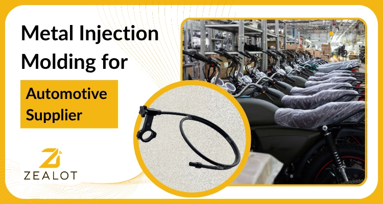
Industry Automotive — Two-Wheeler / Motorcycle Manufacturing
Component Brake Lever Reach Adjuster
Client Profile Tier-1 Automotive Supplier to OEM Assembly Lines
Technology Applied Metal Injection Molding (MIM) — Low-Alloy Steel
Previous Process Conventional CNC Machining
Outcome High-volume daily output, significant per-unit cost reduction, near-zero rejections
Confidentiality Client and OEM identities withheld per NDA. Results based on actual project data.

The Problem

The Problem No One Talks About in Brake Component Manufacturing

Every motorcycle rider trusts their brakes. But few think about the small metal adjuster that lets them position the brake lever at exactly the right distance from the handlebar — the reach adjuster. For riders of different hand sizes, this isn't comfort engineering. It's a safety function.

For a well-established Tier-1 automotive supplier delivering this component to OEM assembly lines across India's two-wheeler market, the reach adjuster had become something unexpected: a production liability.

The part was being machined conventionally. And as motorcycle OEM demand accelerated — driven by expanding model variants across commuter, sport, and premium segments — the limitations of CNC machining were compounding into a genuine business problem.

The Core Question the Client Brought to Us:

"We know MIM exists, but we've never applied it to this category. Can it really handle a brake component — one that goes into a safety-critical assembly on high-volume OEM lines — with the precision, cost, and throughput we need?"

Core Challenges

The Core Challenge: Three Compounding Problems

What the client faced wasn't a single isolated issue. It was three interconnected manufacturing problems, each amplifying the others.

CNC Throughput Could Not Keep Pace with OEM Demand

The brake lever reach adjuster's geometry — adjustment slots, precise hole placements, threaded and stepped features, tight dimensional tolerances — required multiple machining setups per part. Each setup meant tool changes, machine repositioning, and careful operator handling. The result was a production rate that couldn't scale. The client was running CNC machines at full capacity and still falling short of delivery commitments. Scaling up the conventional way — more machines, more operators, more floor space — would have meant heavy capital expenditure for a part that OEMs priced aggressively. The economics didn't work.

Per-Unit Cost Was Incompatible with OEM Pricing Expectations

Automotive supply chains are unforgiving on pricing. OEMs expect year-on-year cost reductions as volumes increase. CNC machining was moving in the opposite direction. As a subtractive process, CNC started with a solid metal billet and cut away significant material to arrive at the reach adjuster's final shape. Material wastage was substantial. High labor input, long cycle times, and accelerating tooling wear made the per-unit cost difficult to defend — especially at the volumes the OEM required. The client needed a process that got cheaper at scale, not one that plateaued or increased.

Geometric Complexity Was Generating Inconsistency and Rejections

The functional geometry of the reach adjuster — the precise slot that enables smooth incremental adjustment, the contact surfaces that must align with the brake lever body, the small structural features holding the assembly together — was difficult to machine consistently across large batch sizes. Multi-step CNC processes accumulate variation. Each setup, each tool change, each operator shift introduces a small but compounding source of deviation. For a brake-system component, even minor dimensional inconsistencies were unacceptable. The client was seeing quality rejections at OEM incoming inspection — and the rework cost was further eroding margins that were already thin.

The Root Cause:

CNC machining is an excellent process for prototypes, low volumes, and parts requiring post-machining. But for a geometrically complex, safety-critical component at automotive OEM volumes and pricing — it is the wrong tool for the job. The client knew this. What they needed was confidence that MIM was the right alternative.

The Solution Logic

Why Metal Injection Molding Is Built for Components Like This

Metal Injection Molding (MIM) combines the design freedom of plastic injection molding with the structural integrity of fully dense sintered metal. The process produces near-net-shape components — meaning the final part geometry is formed directly in the mold, with minimal or no secondary machining required.

For the brake lever reach adjuster specifically, MIM offered a precise match to the problem:

  • Single-cycle geometry: The part's adjustment slots, contoured surfaces, and precision hole features could all be formed in a single molding cycle replacing multiple CNC setups with one controlled operation
  • Near-zero material waste: MIM uses only the feedstock material needed to form the part. Material utilization is dramatically higher than billet machining, which discards significant metal as chips
  • Process repeatability at scale: Once the mold tool is qualified, every part produced is a replica of the last. Part-to-part variation is controlled by the tool and process parameters, not by operator skill or setup variability
  • Throughput advantage: MIM cycle times are far shorter per part than multi-setup CNC operations. A single qualified tool can produce high daily volumes, and additional tools can be added if capacity needs to grow

Our Solution

Our Solution: From Feasibility to Full-Scale MIM Production

The client's engineering team had not previously applied MIM to brake components. They came to us not just for a price quote, but for a manufacturing partner who could assess feasibility, develop the tooling, validate the part, and deliver at production scale. We structured our engagement in four stages.

Stage 1 — Component Feasibility Assessment & Material Selection
We began with a detailed technical review of the reach adjuster's engineering drawings and physical samples from the current CNC process. Our evaluation covered four critical areas:

  • Geometry assessment: The part's adjustment slot, stepped surfaces, and precision holes were confirmed to be well within MIM's capability to form in a single shot, without requiring post-machining
  • Mechanical requirements: The reach adjuster must resist repeated braking forces without deformation. We selected a low-alloy steel MIM feedstock that, after sintering, delivers tensile strength and hardness properties comparable to machined steel — meeting the OEM's material specification without compromise
  • Surface finish confirmation: The adjustment mechanism requires smooth mating surfaces. MIM's as-sintered finish was confirmed to meet the functional requirement, eliminating the need for secondary surface operations
  • Dimensional tolerance mapping: Critical dimensions — lever-to-part mating interface, slot width, hole positioning — were mapped against MIM process capability and confirmed achievable within tolerance

Stage 2 — Precision Mold Tool Design & Development
The mold tool is the foundation of MIM quality. We invested significant engineering effort at this stage because the tool determines everything that follows. Our tool was designed to:

  • Accurately replicate all functional features of the reach adjuster, with engineered compensation for the predictable material shrinkage that occurs during sintering
  • Enable clean, repeatable part ejection without deformation or flash
  • Optimize cycle time for maximum daily output from a single tool
  • Meet production-grade durability standards for long-term, high-volume manufacturing

Stage 3 — Sample Production, Testing & First Article Inspection
Before committing to full-scale production, we produced controlled sample batches for validation. Each sample batch underwent:

  • Full dimensional inspection against the client's engineering drawing
  • Hardness and tensile property testing to confirm material specification compliance
  • Physical trial fit in the actual brake lever assembly to confirm mating, function, and smooth adjustment operation across the full range of positions
  • First Article Inspection (FAI) submission to the client's quality and engineering teams for formal approval

After iterative refinement and sign-off from the client's quality department, the part was cleared for mass production.


Stage 4 — Ramp to Full-Scale Production
With the tool qualified and process parameters locked, production ramped rapidly. The MIM process — injection, catalytic debinding, and high-temperature sintering — runs with minimal operator intervention per part. What previously required multiple machine setups and skilled operator handling now flows through a controlled, automated production sequence.

From Challenge to Results

Results & Outcomes

The shift from CNC machining to MIM delivered measurable improvements across every dimension the client cared about. Here is what changed.

Output: Thousands of Parts Per Day

The most immediate result was the transformation in daily throughput. MIM now produces in volume from a single qualified tool what CNC machining required multiple machines and shifts to approach. The client moved from struggling to meet OEM delivery schedules to operating with comfortable production headroom — able to fulfil large purchase orders reliably and on time.

Quality Consistency: Near-Zero Rejections

Because every part originates from the same precision tool under controlled sintering conditions, part-to-part variation dropped dramatically. The client reported a significant reduction in rejections at OEM incoming inspection. Process capability scores improved, strengthening the client's standing in OEM supplier qualification audits — a critical competitive factor in the automotive supply chain.

Cost Per Part: Substantially Reduced

The switch to MIM delivered a significant reduction in per-unit cost. Material waste dropped to near zero (MIM uses only what's needed to form the part). Fewer process steps replaced the multi-setup CNC sequence. Labor input per part fell sharply at volume. Secondary machining operations were eliminated entirely. Together, these changes allowed the client to meet OEM pricing expectations while protecting their own margins.

Safety Confidence: A Validated, Traceable Process

Safety Confidence: A Validated, Traceable Process The brake lever reach adjuster is directly involved in how a rider operates their brakes. Moving to MIM did not compromise safety — it enhanced manufacturing control. Every production part now comes from a validated, repeatable process with traceable material and process parameters. Both the client and the receiving OEM have greater confidence in the component's in-service reliability.

Takeaways for Automotive Suppliers

Key Takeaways for Automotive Component Manufacturers

Process selection matters

MIM is not a niche alternative to machining — for high-volume, geometrically complex metal components, it is frequently the superior primary process

Safety-critical components are within scope

The brake lever reach adjuster demonstrated that MIM can be applied confidently to safety-critical automotive components, provided tooling, material selection, and validation are engineered rigorously

Cost trajectory is sustainable

The combination of near-zero waste, fewer process steps, and automation-compatible throughput creates genuine commercial impact in OEM supply chains that demand year-on-year cost improvement

Consistency scales with volume

MIM's inherent repeatability — driven by a qualified tool and controlled process, rather than operator variability — naturally generates the consistency that OEM quality systems require

The Bottom Line

Conclusion: Manufacturing Intelligence, Not Just Manufacturing Capacity

The brake lever reach adjuster is exactly the kind of component MIM was engineered for: small, geometrically intricate, mechanically demanding, and required in volumes that expose every inefficiency in a conventional machining process.

What was a production bottleneck for our client is now one of their most efficiently manufactured components — flowing reliably into the assembly lines of well-known motorcycle OEM brands, at a cost structure that works, with a quality record that strengthens their supplier position.

Our contribution went beyond quoting a price per piece. We brought engineering expertise in feasibility analysis, tool design, material selection, process validation, and quality assurance — making the transition from CNC to MIM fast, controlled, and commercially impactful.

That is what a genuine manufacturing partnership looks like.

Is Your Component a Candidate for MIM?

If you manufacture small-to-medium metal components with complex geometry, tight tolerances, or high-volume requirements — and your current process is creating cost pressure, throughput limitations, or quality variability — we would like to evaluate your component. Reach out to the Zealot Inc. engineering team to begin a no-obligation feasibility discussion.

Schedule a Technical Consultation

Engineering Consultation

Ready to Evaluate Your Component for MIM?

Reach out to the Zealot Inc. engineering team to begin a no-obligation feasibility discussion. We assess geometry, mechanical requirements, tolerances, and production volumes to determine MIM suitability — typically within 5–7 business days.

Call us : +91 99094 18224
Email us : sales@zealotinc.net

FAQs: Metal Injection Molding for Automotive Components

1. What is Metal Injection Molding (MIM) and how does it work for automotive components?
Metal Injection Molding (MIM) is a manufacturing process that combines the design flexibility of plastic injection molding with the mechanical strength of sintered metal. Metal powder is mixed with a binder to create a feedstock, which is then injected into a precision mold. The binder is removed through a debinding stage, and the part is sintered at high temperature to achieve full density. For automotive components, MIM enables complex geometries, tight tolerances, and high daily output volumes — making it well-suited for parts like gear mechanisms, control components, and fasteners that are too intricate to machine economically at scale.

2. Can MIM be used for safety-critical automotive components like brake parts?
Yes. MIM is actively used in safety-critical applications across automotive, medical, and aerospace industries. The key requirement is rigorous process validation: proper material selection (typically low-alloy or stainless steel meeting OEM mechanical specifications), precision tool design that accounts for sintering shrinkage, controlled process parameters, and First Article Inspection (FAI) approval before production. When these steps are followed, MIM delivers consistent, repeatable parts that meet or exceed the quality standards required for brake system components.

3. Why is MIM more cost-effective than CNC machining for high-volume small metal parts?
CNC machining is a subtractive process — it starts with a solid billet and removes material to form the part. For components with complex geometry, this means significant material waste, multiple setups, high labor input, and slow cycle times. At high volumes, these costs compound. MIM is an additive near-net-shape process — it uses only the material needed to form the part, produces all geometric features in a single cycle, requires minimal operator intervention per part, and typically eliminates secondary machining. The result is a cost structure that improves as volume increases, not one that plateaus.

4. How long does it take to qualify a new MIM component for production?
Typical timelines from component feasibility review to First Article Inspection (FAI) approval range from 10 to 16 weeks, depending on part complexity, mold tool development requirements, and the number of validation iterations needed. Standard machines: 8–12 weeks; custom or complex geometries: 12–16 weeks. Zealot's MIM engineering team provides a component-specific timeline at feasibility stage.

5. What types of components are best suited for Metal Injection Molding?
MIM performs best for components that are small to medium in size (typically under 100g), geometrically complex with features like internal slots, threads, undercuts, or contoured surfaces, produced in volumes of 10,000 or more units per year, and require mechanical properties (hardness, tensile strength, wear resistance) achievable in sintered steel alloys. Common applications include gear mechanisms, fasteners, medical device components, two-wheeler handlebar controls, defence hardware, and precision electronics parts.

6. What materials are available for MIM components?
Zealot Inc. offers a range of MIM-compatible materials including low-alloy steel (for automotive and mechanical applications requiring high strength), stainless steel (for corrosion resistance in medical, food, and marine environments), tool steel (for wear-resistant applications), tungsten alloys (for high-density applications), and titanium alloys (for lightweight, high-strength requirements). Material selection is determined during the feasibility assessment based on the component's mechanical and environmental service requirements.
Share
Zealot_Logo_3

Zealot delivers advanced polyurethane, nylon, and automation solutions with precision-engineered systems, turnkey plants, and global expertise.

Quick Links
  • About Us
  • Metal Injection Molding
  • Blogs
  • Case Studies
Business Verticals
  • Cast Polyurethane Elastomer Solution
  • Cast Nylon Solutions
  • Machinery Accessories
  • Precision Metal Component Solutions
Contact

+91 9909418224
sales@zealotinc.net

3, Ambica Industrial Estate, Nr Kothari cross road, rakanpur- santej, Gandhinagar, Gujarat, India, 382721.

© Copyright 2026. Zealot, All Rights Reserved | Developed & Marketed by Wolfable
✕
Zealot_Logo_1
  • Home
  • About
  • Busniess Verticals
    • Cast Polyurethane Elastomer Solution
      • Automatic Cast Polyurethane Elastomer Solution
      • Hand Batch Cast Polyurethane Elastomer Solution
    • Cast Nylon Solutions
    • Machinery Accessories
      • Metering Pump
      • Industrial Hose
      • Pressure Tank
    • Precision Metal Component Solutions
  • MIM
  • Support
    • Consulting
    • Assistance
    • Turnkey Project Solutions 
  • Resource
    • Blogs
    • Case Study
    • Downloads
    • Videos
  • Contact Us